The measured speech quality
The level at which test signals are played into a network significantly influences the measured speech quality. Telephone networks are typically optimised for a narrow range of voice levels. Playing at the right or wrong level can mean the difference between achieving a maximum 4.5 score or a failing 2.75 score.
Did you know? Research in the 1970's at the United Kingdom Post Office determined that, in a controlled physical environment, the standard deviation of speech levels between different talkers was around 2.8dB. Measured on real networks, where varying background noise and telephones are used, this distribution increased to 4.8dB. This translates to over 67% of conversations being within a 10dB range, and over 95% within 20dB. Although this research is old, the distribution has probably not changed much over the years.
The average speech level in the core network is around -20dBm0. (dBm0 describes the level relative to the 0dBr point in the network.) The problem is that, in most cases, the tests we perform are from outside the network and the level we play at will be attenuated or amplified before it reaches the 4-wire part of the network.
Connected via VoIP, ISDN, handset port to a desk phone or a hands-free kit of a cell phone
 So what level should we use? If we are connected via a phone-line port, VoIP or ISDN then in most cases we can just set the required test level in the tasklist. When connected via a handset port to a desk phone or a hands-free kit of a cell phone, it becomes more difficult because we do not know the gain or attenuation of the phone.
If you are able to measure the level in the 4-wire part of the network then you can adjust the play level until you achieve close to –20dBm0. Note: you do not need to change your tasklist for this, you can simply adjust the Level Offset in your node configuration. Changing Level Offset is shown later in the article.
When it is not possible to measure the level within the network, then this practical procedure for finding the “best” level has worked well in many situations.
Instructions : The “best” level can be identified by repeating a speech quality test at different levels
If the level is too low then the noise floor will degrade the speech quality score. If the level is too high then amplitude clipping will degrade the score. The optimum level will be a point somewhere between these extremes. The “best” level can be identified by repeating a speech quality test at different levels, starting at a very low level and increasing in 3dB steps, using the tasklist here. Note that this works with English as the locale - there are issues with Chinese and German language operating systems. These will be resolved soon.
To start the test, make a call between the handset under test and another device. An analogue line or good quality IP phone is preferred. If the device at the other end of the call has a volume control, set volume to around 80% of maximum. Run the test by dragging the node attached to the device to be calibrated, to the other node.
After the test has completed we want to view how the speech quality has changed with level. This is best done by running a Trend Report on the completed test. To run the trend report, right click on the completed test in the Test Manager and select Generate Report.
In the Report Generator panel,select Trend report and Level Calibration profile. This will generate a report that looks like this:

POLQA NB graph
The POLQA NB graph in the upper left-hand corner shows clearly how level alone influences the measured speech quality. The curve may be smooth or erratic, depending on network type and conditions. If the curve is erratic, try repeating the test one or more times.
Estimate the position where the optimum speech quality occurs. Double click on the curve at this point to drill down and then click on the icon in the last column to open the result into Results Analyser.

Notice the Level Offset value in Results Analyser ‘Task’ window:
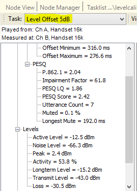
We now apply this to the Node Configuration’s Level Offset as shown below, and then run a quick quality check to confirm that we achieve the expected speech quality.

The effects of any Automatic Gain Control (AGC) hysteresis may mean that some adjustment to this value is needed - this can only be determined by experimenting with small adjustments either side of the calculated level offset figure.
Contact Opale Systems or your distributor for more information.